62 FL Chop Rebuild 3
Link Back to '62 FL new page 2
Continuing the front disk brake adapter
Continuation from page 2...
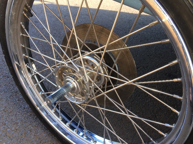
Building a front disk brake adapter for my narrowed glide
with a star hub....
Need some lathe time to turn this down to fit,
as described on page 2....
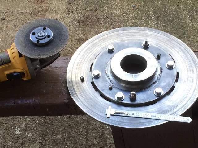
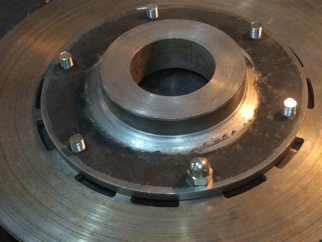
Finally got some lathe time with my friend at the local machine shop!
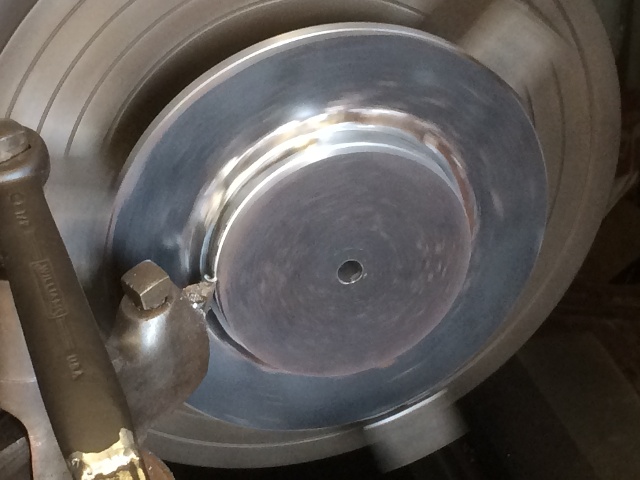
Chucked it in the lathe on the smaller disk and cut the OD
of the larger disk to size....
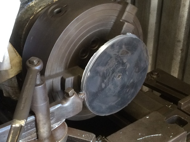
Then cut the face to provide the step for the disk brake
rotor to ride on....
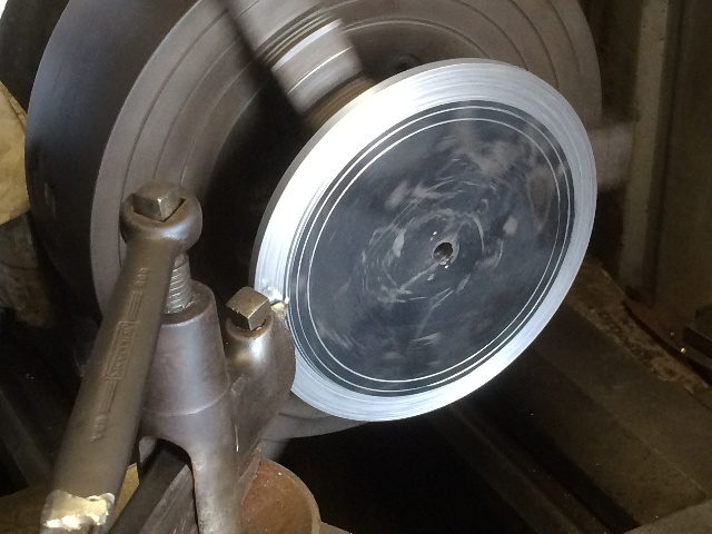
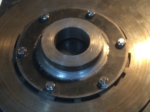
We got a perfect fit!
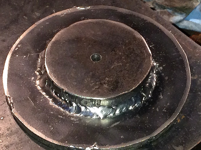
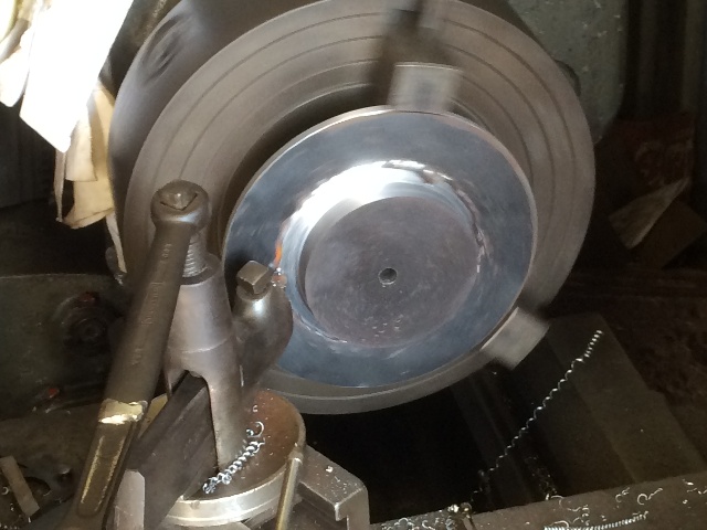
Flipped the piece over and cut the OD of the smaller disk to fit the star hub...
Smoothed out and beveled the weld while we were at it....
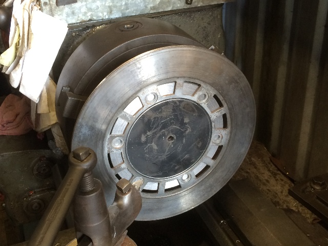
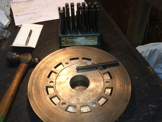
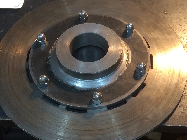
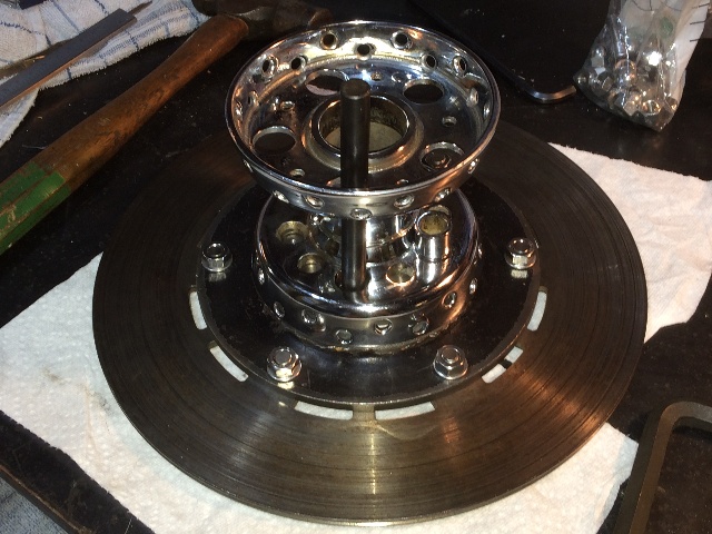
Then ran a couple different sizes of drill bits through the center to get it big enough to start
machining it internally with a tool to a size to fit on the brake hub portion of the star hub....
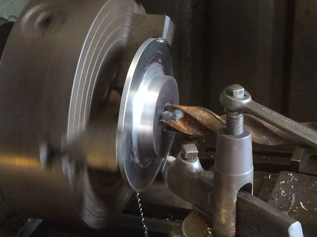
Didn't manage to get a pic of the internal cutting,
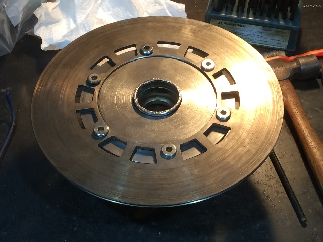
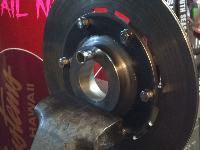
But we got an excellent fit on the star hub...
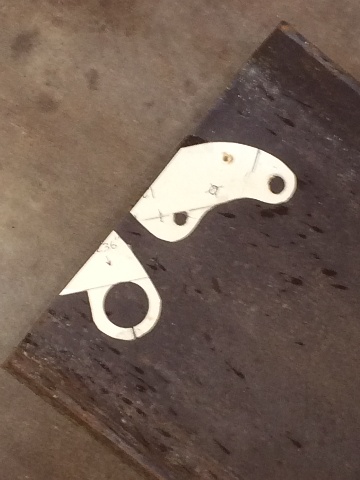
Now I have to drill and tap for the bolts,
And fab the bracket to carry the caliper.
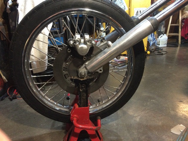
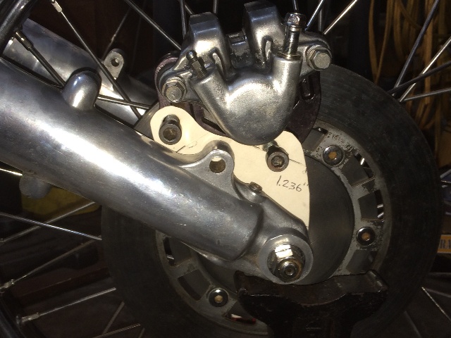
This view is on the left side of the front forks.
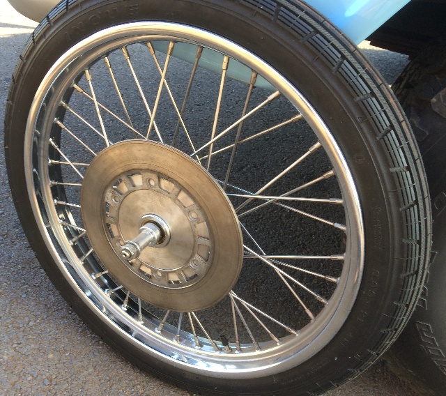
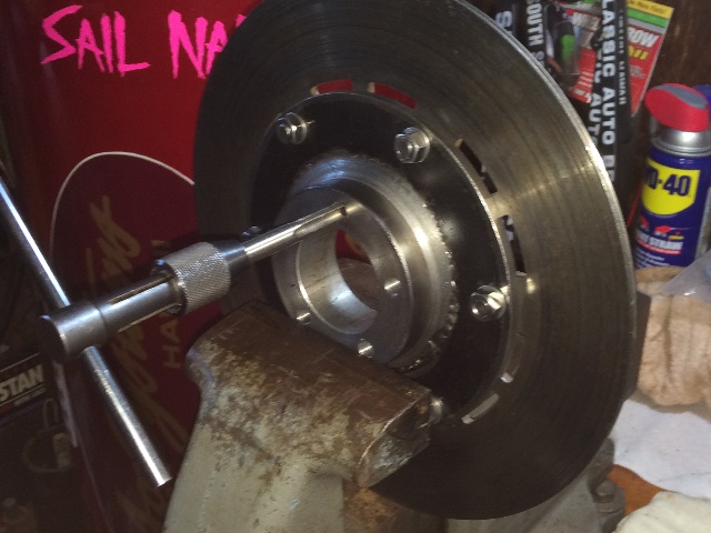
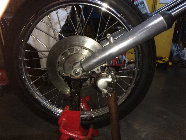
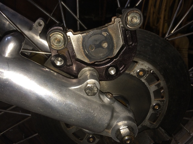
The view from the right side...
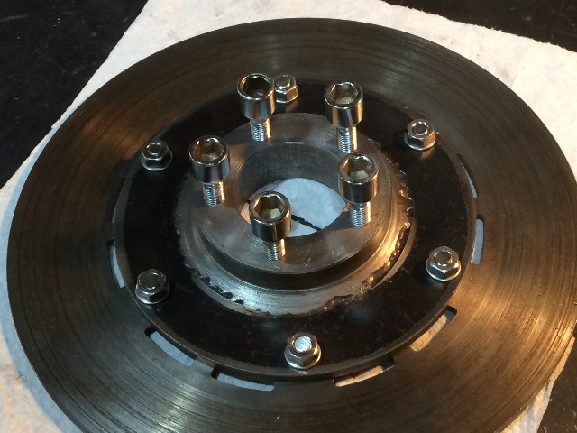
The bolts for the original Suzuki rotor are allen head, 8 mm, 1.25 thread.
There is also a 10 mm shoulder on the bolts that fits the 10 mm holes in the rotor, and locks
into the disk carrier an additional 2 mm before the 8 mm thread starts in the carrier.
My transfer punches are all US, but the 13/32" punch fits nicely in the 10 mm hole,
and allows me to accurately center punch the six holes.
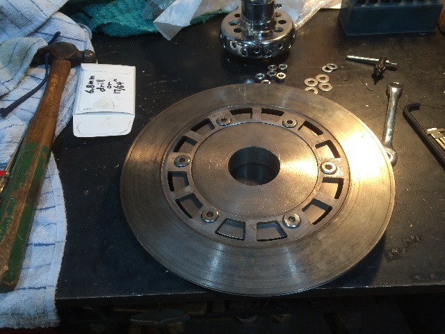
Punched, drilled and tapped 2 holes opposite each other.
The tap is an 8 mm, 1.25 thread, so trying to find a starter hole size for the tap
was a bit of a problem. A 6.8 mm drill was spec'd, or 0.268".
A 17/64" bit was used, it is 0.266", just slightly tight for this tap,
But by using a good quality cutting oil, and working the tap through
the metal carefully, it went very well.
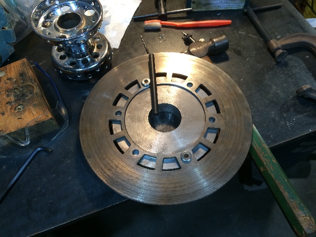
Drilled the center punches first with a small bit, I used a 3/32" on this one.
Then followed up with the 17/64" drill, then ran the tap through.
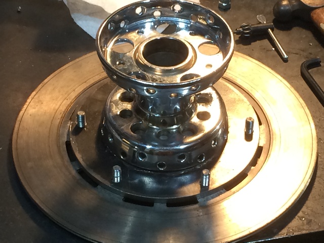
The disk carrier has not been countersunk yet for the shoulder on these bolts,
so flipped the rotor over and put the bolts in for now from the back side just to check it all out.
The bolts are a bit long, and looks like there may be some interference with the spokes.
But I need to get a 10 mm drill to countersink the carrier holes a bit for the shoulders
on these bolts, then I can figure the total bolt length I can get away with on this setup.
Just some pix of the 8 mm tap and the bolts thenselves.
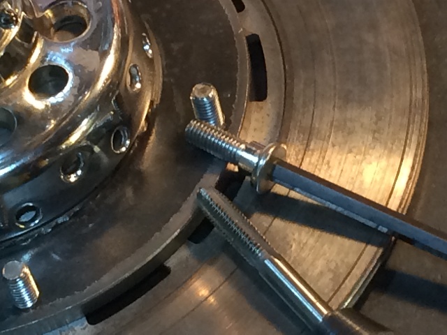
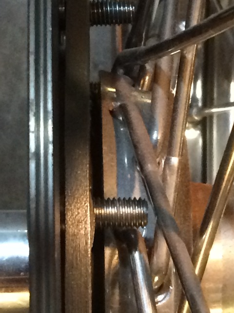
Here you can see why I need to countersink the 10 mm hole into the carrier
to accomodate that shoulder on the bolt....
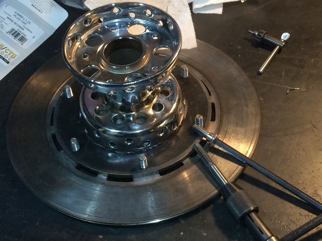
Checking the backside bolt length, needs to be shortened slightly,
but the carrier needs to be countersunk first, with the rotor flipped over
which will expose more thread. Want to run some ss acorn bolts on these threads.
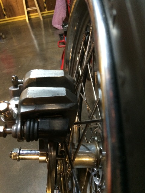
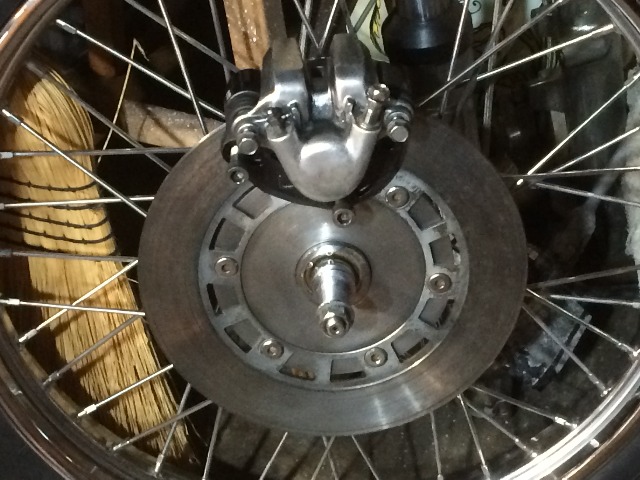
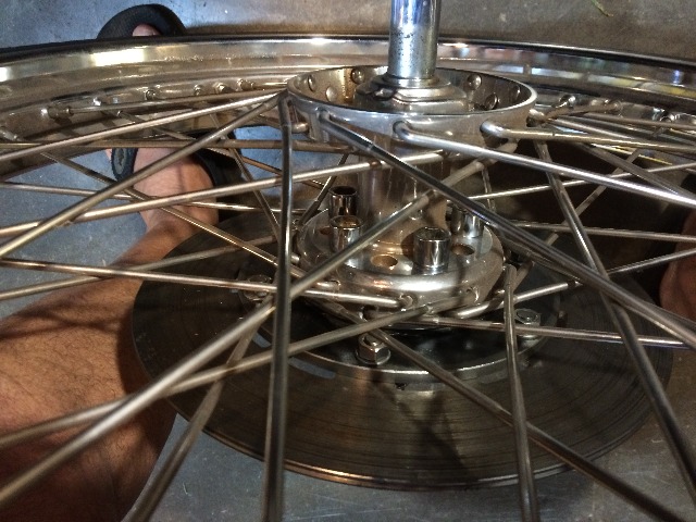
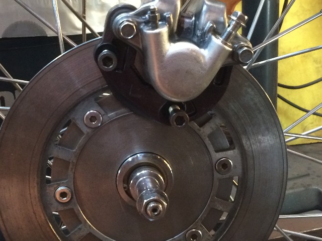
Put the caliper on to check it out, looks good and clears the spokes.

When it is all setup and pressurized will be the final check.
Since the piston is on the outside, the floating caliper will move
away from the spokes as the pads wear down.
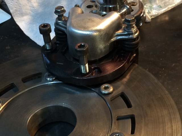
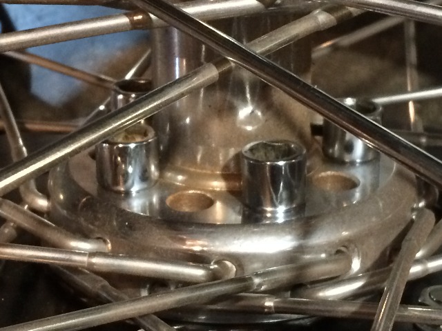
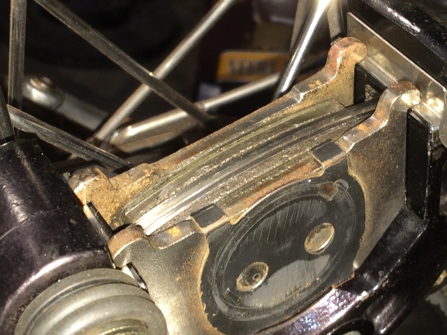
Here the bolt heads are exposed because the carrier holes have not been
countersunk yet, they will be flush with the rotor once the countersunk holes
have been drilled and the rotor flipped over to accommodate the flats on the bolt heads.
Countersunk the bolt holes on the rotor side with a 25/64" drill,
seemed to work well for the 10 mm shoulder on these rotor bolts....
Then two washers and a hex nut provided the correct height on the bolt threads
to shorten them for the acorn nuts....
Perfect fit....
I think this would look good on the spoke side of the brake rotor,
but unfortunately they were just a hair too close to the spokes, so will have to
just run the hex nuts....
The other alternative is to machine a spacer where this center hub fits
into the wheel's star hub to move it out just enough to have the
acorn nuts clear the spokes. I tried positioning the brake carrier
in many positions, but no matter where I put it, at least one or
more of the acorn nuts would hit a spoke and tilt the carrier slightly
preventing it from seating correctly in the star hub !
A thin spacer inside the star hub would correct that.
The rotor side looks great with the rotor flipped to it's correct side
and the bolts counter sunk into the carrier the correct depth....
Double checking everything for a good fit....
I want to run either flat washers or lock washers under these hex nuts to
bring them out to be flush with the end of the threads....
But they clear the spokes just fine....
Now to drill and tap the carrier for the 3/8" - 20 threads on the wheel bolts.
As that is a "special" HD thread, I have ordered a pair, a plug tap and a
bottom tap.
The taps came in, so I transfer punched, drilled and tapped one hole, and
it was a perfect fit on the star hub....
In my tool drawer I have two standard 3/8" taps, a 3/8"-16 NC that requires a 5/16" drill (0.3125")
and a 3/8"-24 NF that requires a Q drill (0.332") and I could not find a reference
for the drill size for this 3/8"-20 tap, so I tried a 21/64" drill (0.328") and the tap was tight
on that first hole, but I got it done....
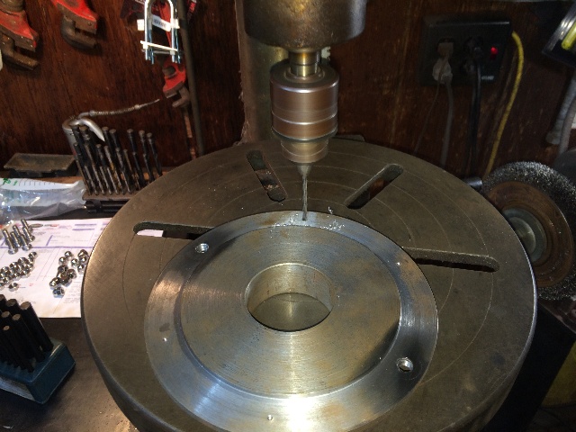
Since that first hole was really too tight for the tap, I moved up to a Q bit (0.328)
I transfer punched the other four holes, and drilled the 1/16" centering holes.
Drilled the four holes with the "Q" drill bit and tapped them.
The taps felt right this time, not too tight or too loose.
These are blind holes, drilled roughly 1/8" deeper than the HD wheel bolt threads.
Ran the plug tap in first, then the bottom tap to run clean threads all the way down.
The bolts all go in perfectly, and go all the way in, no problem...
The bolts and holes matched up perfectly to the star hub on the 21" wheel I'm going to use!
Just a closer look, I should never have a problem with this....
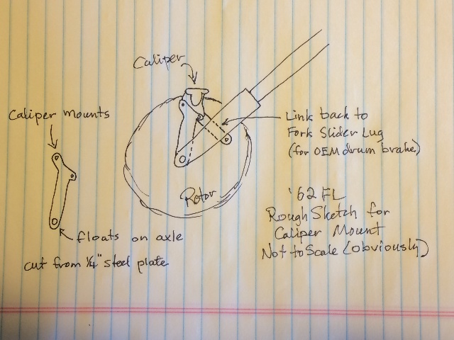
Now to design and fabricate the bracket to mount the caliper on.
This is roughly the position for the caliper, up slightly, it's sitting on the disk now.
A rough sketch of what I am thinking, a bracket that floats on the axle to provide
vertical position, then a link to the old drum brake tab on the fork slider.
All cut from 1/4" steel.
Put the front forks together, put the wheel and brake rotor on,
and propped up the axle so the wheel can spin....
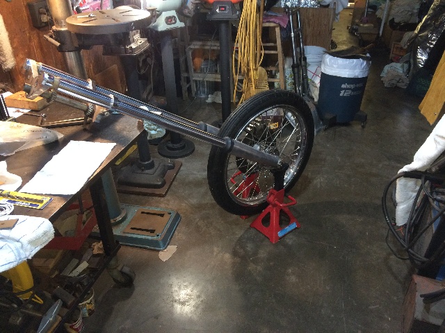
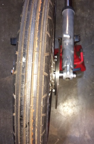
Here you can see how tight this space in, 1"....
I got that rotor right where I want it !
AND, it spins true, no wobble at all....
The caliper looks good up here....
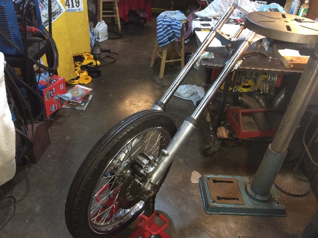
Maybe a little further back, almost touching the fork leg....
Or maybe it should go under the fork leg ??
It looks like the mounting bracket would be smaller and fit better in this location....
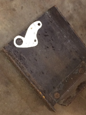
Made a cardboard template, it's not precise, but shows the general idea...
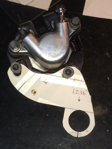
It tucks in nicely behind the fork, and that brake lug on the left slider
fits nicely to the frame for the caliper...
Now to transfer that to 1/4" steel.
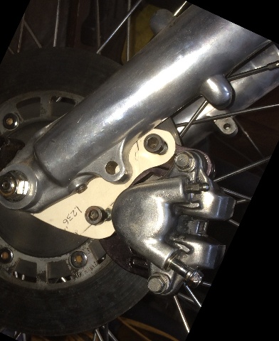
The first step is to get the frame for the caliper correctly located,
and drill and tap a hole in it for the anchor bolt on the fork slider.
Decided I needed to be able to more accurately align the pads with the rotor, so I
pulled off the caliper but left the pads loaded in the frame, transfer punched the center of
the fork slider hole to the caliper frame after the pads were accurately lined up...
Transfer punched the center of the fork slider brake lug to the caliper frame,
Then drilled and tapped it for a 7/16" fine thread, and bolted it up with a 1/4"
thick washer as a spacer, as the final caliper support down to the axle will be 1/4".
The two original holes in the caliper frame were 10mm fine, drilled them and
retapped them also to 7/16" fine.
I'm looking for some ss 7/16" fine thread allen head bolts to use on this, the cap screws are ok for now though...
Pulled a piece of 1/4" thick channel out of the scrap pile to cut the final piece.
There is a bit of a problem here though, as the fork slider brake anchor tab
is not in alignment with where the part that fits on the axle, so they will be two
separate pieces that will be aligned and welded back together.
More later on the front disk brake setup on page 4.....